KS102-2 Ultrasonic Phantom, Ophthalmology B-ultrasound Model (3pcs/set)
Mode:KS102-2
Type:QA-Phantom
Contact: ken@hkmedqc.com
KS102-2 Ultrasonic Phantom, Ophthalmology B-ultrasound Model.PDF
")
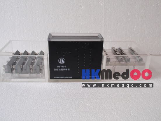
KS102-2 Ophthalmic Ultrasound Phantom (3-Piece Set)
(A) Artificial Tissue Ultrasound Model (KS102-2)
1. Internal structure
(1) Standard medium
A TM material is filled in the six-sided cavity formed by the four walls and the bottom plate and the sound window. This serves as the standard medium.
(2) Linear target system
Three groups of nylon linear targets are embedded within the TM material, including:
(a) Blind zone target group: There are a total of 5 target lines, and their depths (distance from the sound window) are 1, 2, 3, 4, and 5 mm respectively;
(b) Longitudinal linear target group: There are a total of 3 groups of target lines, each with 12 lines, and their depths (distance from the sound window) start from 5 mm, 7.5 mm, and 10 mm, with one line every 10 mm;
(c) Transverse linear target group: The depths (distance from the sound window) are 20 mm and 40 mm, and there are a total of 8 target lines, with an interval of 10 mm between adjacent target lines.
(3) Mimic cyst structure
Diameter 2 mm cylinder: 5 pieces, the axes are parallel to the target lines, and they are located at depths of 10, 20, 30, 40, and 50 mm respectively;
2. Technical indicators
(1) TM material
Sound velocity: (1540 ± 10) m/s
Sound attenuation coefficient: (0.5 ± 0.05) dB/cm/MHz
(2) Nylon wire target
Target wire diameter: (0.3 ± 0.02) mm
Geometric position tolerance: ± 0.1 mm
(B) Axial Resolution Test Specimen
1. Structural form
The single-piece structure of the axial resolution test piece is shown in Figure 3. The different-sized "gaps" used for measurement are separated by thin plastic sheets placed horizontally. When filled with a liquid with a sound velocity of 1540 m/s, they are in a standard state. Above the gap is a plastic sheet about 2.0 mm thick and high, which is sound-absorbing. Below it is a 10 mm thick glass plate, and the lower surface of the glass plate has grooves to reduce the echoes at the interface behind the glass plate.
All the metal parts in this test piece are made of stainless steel. The outer shell is made by bonding an organic glass plate. The internal transverse dimensions are just large enough to accommodate one test piece. In the depth direction, the size above the observation object (the gap) is not less than the scanning depth of an ophthalmic B-ultrasound.
2. Technical indicators
Number of "gaps": 8
Values of "gaps": 0.05, 0.1, 0.2, 0.3, 0.4, 0.5, 0.6, 0.7 mm
Tolerance of "gaps": <10%
(C) Sideward Resolution Test Specimen
1. Structural form
The individual structure of the lateral resolution test piece is shown in Figure 4. The different sizes of "gaps" used for measurement are separated by thin plastic sheets placed vertically. When filled with a liquid with a sound velocity of 1540 m/s, they are in a standard state. On both sides of the "gaps" are 10 mm thick polymer plastic plates. Each plate has an outwardly cut 45° slope on the upper surface to eliminate the original path echoes. To position the two measurement objects of different resolutions at the same height, three metal "legs" are installed below the acrylic plate of the axial resolution test piece.
All the metal parts in this test piece are made of stainless steel. The outer shell is fabricated and bonded using acrylic plates. The internal lateral dimensions are just large enough to accommodate two sets of individual structures. In the depth direction, the size above the observation object (the gap) is not less than the scanning depth of an ophthalmic B-ultrasound. 2. Technical indicators
Number of "gaps": 8
Values of "gaps": 0.1, 0.2, 0.3, 0.4, 0.5, 0.6, 0.7, 0.8 mm
Tolerance of "gaps": <10%
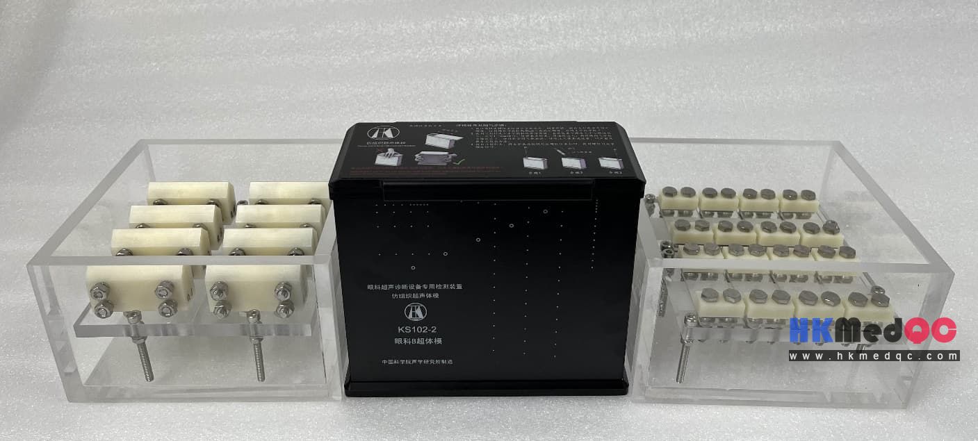
The KS102-2 Ophthalmic Ultrasound Phantom is a professional tissue-mimicking QA device designed specifically for performance calibration and image quality verification of ophthalmic B-scan ultrasound systems (10–25 MHz). Ideal for eye clinics, ophthalmic equipment manufacturers, and metrology labs, this 3-piece set simulates human ocular tissue acoustic properties for accurate, repeatable testing.
Crafted from high-stability TM (tissue-mimicking) material, the phantom features a speed of sound of 1540±10 m/s and acoustic attenuation coefficient of 0.5±0.05 dB/cm/MHz at 23±3°C, complying with YY0773-2010 and international ultrasound standards. It integrates precision nylon wire targets (0.3±0.02 mm diameter) and simulated cyst structures for comprehensive testing.
Key Test Structures:
- Dead zone targets: 5 wires at 1–5 mm depth
- Axial resolution targets: 3 groups of 12 wires each (5–10 mm initial depth, 10 mm spacing)
- Lateral resolution targets: 8 wires at 20/40 mm depth (10 mm spacing)
- Simulated cysts: Five 2 mm diameter cylinders at 10–50 mm depth
(A) Artificial Tissue Ultrasound Model (KS102-2)
1. Internal structure
(1) Standard medium
A TM material is filled in the six-sided cavity formed by the four walls and the bottom plate and the sound window. This serves as the standard medium.
(2) Linear target system
Three groups of nylon linear targets are embedded within the TM material, including:
(a) Blind zone target group: There are a total of 5 target lines, and their depths (distance from the sound window) are 1, 2, 3, 4, and 5 mm respectively;
(b) Longitudinal linear target group: There are a total of 3 groups of target lines, each with 12 lines, and their depths (distance from the sound window) start from 5 mm, 7.5 mm, and 10 mm, with one line every 10 mm;
(c) Transverse linear target group: The depths (distance from the sound window) are 20 mm and 40 mm, and there are a total of 8 target lines, with an interval of 10 mm between adjacent target lines.
(3) Mimic cyst structure
Diameter 2 mm cylinder: 5 pieces, the axes are parallel to the target lines, and they are located at depths of 10, 20, 30, 40, and 50 mm respectively;
2. Technical indicators
(1) TM material
Sound velocity: (1540 ± 10) m/s
Sound attenuation coefficient: (0.5 ± 0.05) dB/cm/MHz
(2) Nylon wire target
Target wire diameter: (0.3 ± 0.02) mm
Geometric position tolerance: ± 0.1 mm
(B) Axial Resolution Test Specimen
1. Structural form
The single-piece structure of the axial resolution test piece is shown in Figure 3. The different-sized "gaps" used for measurement are separated by thin plastic sheets placed horizontally. When filled with a liquid with a sound velocity of 1540 m/s, they are in a standard state. Above the gap is a plastic sheet about 2.0 mm thick and high, which is sound-absorbing. Below it is a 10 mm thick glass plate, and the lower surface of the glass plate has grooves to reduce the echoes at the interface behind the glass plate.
All the metal parts in this test piece are made of stainless steel. The outer shell is made by bonding an organic glass plate. The internal transverse dimensions are just large enough to accommodate one test piece. In the depth direction, the size above the observation object (the gap) is not less than the scanning depth of an ophthalmic B-ultrasound.
2. Technical indicators
Number of "gaps": 8
Values of "gaps": 0.05, 0.1, 0.2, 0.3, 0.4, 0.5, 0.6, 0.7 mm
Tolerance of "gaps": <10%
(C) Sideward Resolution Test Specimen
1. Structural form
The individual structure of the lateral resolution test piece is shown in Figure 4. The different sizes of "gaps" used for measurement are separated by thin plastic sheets placed vertically. When filled with a liquid with a sound velocity of 1540 m/s, they are in a standard state. On both sides of the "gaps" are 10 mm thick polymer plastic plates. Each plate has an outwardly cut 45° slope on the upper surface to eliminate the original path echoes. To position the two measurement objects of different resolutions at the same height, three metal "legs" are installed below the acrylic plate of the axial resolution test piece.
All the metal parts in this test piece are made of stainless steel. The outer shell is fabricated and bonded using acrylic plates. The internal lateral dimensions are just large enough to accommodate two sets of individual structures. In the depth direction, the size above the observation object (the gap) is not less than the scanning depth of an ophthalmic B-ultrasound. 2. Technical indicators
Number of "gaps": 8
Values of "gaps": 0.1, 0.2, 0.3, 0.4, 0.5, 0.6, 0.7, 0.8 mm
Tolerance of "gaps": <10%
SAG: Ophthalmic Ultrasound Phantom,KS102-2 Phantom,Eye B-Scan Calibration Phantom,Tissue-Mimicking Ultrasound Phantom,10-25MHz Ophthalmic QA Phantom,Ocular Ultrasound Test Device,Medical Ultrasound Probe Calibration