KS107QN-1 Intracavitary Scanning Ultrasound Model,KS107QN-1 Phantom
Mode:KS107QN-1
Type:QA-Phantom
Contact: ken@hkmedqc.com
KS107QN-1 Intracavitary Scanning Ultrasound Model,KS107QN-1 Phantom.PDF

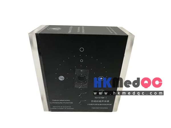
The KS107QN-1 internal scanning ultrasonic body model is a standard body model specifically designed for testing the imaging characteristics of B-type ultrasonic diagnostic equipment. It complies with standards such as GB 10152-2009 and YY/T 0906-2013. The internal part is filled with ultrasonic tissue-like materials and includes various test targets, such as target lines, simulated cysts, stones, and simulated tumors. The body design features a 12.5mm internal probe scanning through-hole, which can be used to evaluate various parameters of the ultrasonic imaging device, such as blind zone, resolution, and geometric position accuracy. This body model is suitable for evaluating the performance of B-ultrasound imaging devices that are equipped with internal ultrasonic probes.
Standards:
GB 10152-2009 B-type Ultrasound Diagnostic Equipment
YY/T 0906-2013 Test Methods for Performance of B-type Ultrasound Diagnostic Equipment with Intra-Cavity Probes
YY/T 1659-2019 General Technical Requirements for Intravascular Ultrasound Diagnostic Equipment
Application Scope:
The KS107QN-1 internal scanning ultrasonic body model is a human physical model that mimics the ultrasonic propagation characteristics of tissues. It is a testing device composed of ultrasonically tissue-mimicking material (referred to as TM material) and various test targets embedded within it (including target lines, simulated cysts, stones, simulated tumors), as well as sound windows, shells, and indicative decorative panels.
The center of the phantom is equipped with a scanning hole with an inner diameter of 12.5mm, which is used to insert an intracavitary probe for ultrasound scanning. It is specifically designed to examine the imaging characteristic parameters of the B-ultrasound imaging device that is connected with an intracavitary ultrasound probe, including blind zone, lateral (transverse) resolution, axial (longitudinal) resolution, lateral geometric position accuracy, axial geometric position accuracy, and the diameter error of the simulated lesion.
According to the technical requirements of the general body model in the national standard GB10152-2009, the technical parameters of the body model are as follows:
1. Sound velocity of TM material: 1540 ± 10 m/s (23 ± 3℃)
2. Slope of sound attenuation coefficient of TM material: 0.70 ± 0.05 dB/cm/MHz (23 ± 3℃)
3. Diameter of nylon target line: 0.3 ± 0.05 mm (Note: For lateral resolution E1-E3 target groups with an interval of 0.5 mm, 0.15 ± 0.02 mm is adopted)
4. Position tolerance of nylon target line: ± 0.1 mm
Product Introduction:
B-type ultrasound diagnostic equipment for in-vessel scanning and detection device
Technical Specifications:
1. The four walls and the bottom are made of organic glass and assembled. The outer surfaces of the four walls are covered with plastic film panels for indication and decoration.
2. The dimensions are 17cm x 16cm x 66cm.
3. The bottom plate is equipped with two circular holes with a diameter of 3.6 cm, which are sealed with rubber sheets for the purpose of injecting maintenance fluid and removing air.
4. It is filled with TM material that meets the requirements of national standards as the standard sound transmission medium.
5. At a depth of 80mm from the upper edge, there is a scanning hole with a diameter of 12.5mm in the center for the internal probe. The probe is inserted into this hole for ultrasonic scanning.
6. Linear Target System
The TM material is embedded with a group of wire targets numbered 5. Their distribution is shown in the attached figure, and there are a total of:
(1) A: Blind zone target group. There are a total of 8 target lines, with one set at every 45°. The setting depth starts from 2mm above the edge of the central probe scanning hole, with a step size of 1mm, and is 2, 3, 4, 5, 6, 7, 8, and 9mm respectively.
(2) B1-B3: Axial lateral resolution target group. The lateral branches are respectively 10, 30, and 50 mm away from the lower edge of the central scanning hole. In groups B1 and B2, B3, the target lines are distributed on arcs centered at the center of the scanning hole with radii of 16.25 mm, 36.25 mm, and 56.25 mm, respectively. The lateral linear distance between the centers of two adjacent target lines is successively 4, 3, 2, and 1 mm. The difference in the radius from the center of the scanning hole to the centers of two adjacent target lines is 3, 2, 1, and 0.5 mm, and the horizontal distance is 1 mm.
E1-E3: Lateral resolution target groups. The target groups are located 10, 30, and 50 mm below the lower edge of the center scanning hole. In groups E1 and E2, and E3, the target lines are distributed on arcs centered at the center of the scanning hole with radii of 16.25 mm, 36.25 mm, and 56.25 mm respectively. The lateral distance between the centers of two adjacent target lines is 0.5 mm.
(3) C1-C2: Lateral target groups (used to evaluate lateral (horizontal) geometric position accuracy). The lateral target groups are located 20 and 40 mm below the upper edge of the center scanning hole. In each group, the lateral distance between the centers of the target lines (the straight-line distance between the two target lines) is 10 mm. The target lines are distributed on arcs centered at the center of the scanning hole with radii of 26.25 mm, 46.25 mm. At 20 mm, the lateral target group is distributed in a semi-circular shape starting from the left horizontal position of the scanning hole, with a total of 9 target points. At 40 mm, the lateral target group is distributed in a semi-circular shape starting from the left horizontal position of the scanning hole, with a total of 15 target points.
(4) D: Longitudinal target groups. There are 6 target lines in the longitudinal target group, located 10, 20, 30, 40, 50, and 60 mm below the center of the scanning hole. The distance between the centers of adjacent lines is 10 mm.
7. Simulated Lesions
(1) F1 - F3: Mimic of Cyst Structure: TM material contains 3 simulated cystic lesions embedded within it. All are cylindrical in shape, with diameters of 2, 4, and 6 mm respectively. The axes of the cylinders are parallel to the target line, and the centers are located at 10, 30, and 50 mm above the edge of the central scanning hole, respectively.
(2) G: Mimic of Tumor, located at the left horizontal position of the central scanning hole, 25 - 35 mm away from the edge of the central scanning hole, cylindrical in shape, with a diameter of 10 mm, and the axis is parallel to the target line.
(3) H: Mimic of Cyst and Calculus, the mimics of the cysts are cylindrical, located at the right horizontal position of the central scanning hole, 25 - 35 mm away from the edge of the central scanning hole, with a diameter of 10 mm, and the axis is parallel to the target line. The mimics of the calculus are irregular in shape, located in the middle of the cyst, with the maximum size approximately 4 - 6 mm.
KS107QN-1 Intracavitary Scanning Ultrasound Body Model
Standard Configuration:
1 ultrasound body model
1 portable box,
1 test report
SAG: Tissue Ultrasound Phantom,KS107QN-1,Ultrasound Calibration,Medical Phantom,Imaging Quality Test,Ultrasonic Tissue Mimic,QA Phantom,Ultrasound Probe Calibration,Biomedical Phantom,Diagnostic Ultrasound