KS107QN-4B Internal Cavity Scanning Ultrasonic Body Model,KS107QN-4B Phantom
Mode:KS107QN-4B
Type:QA-Phantom
Contact: ken@hkmedqc.com
KS107QN-4B Internal Cavity Scanning Ultrasonic Body Model,KS107QN-4B Phantom.PDF

The KS107QN-4B type internal cavity scanning ultrasonic body model is a human physical model that mimics the ultrasonic propagation characteristics of tissues. It is a testing device composed of Ultrasonically Tissue-Mimicking Material (referred to as TM material) and various test targets embedded within it (including target lines, simulated cysts, simulated stones, simulated tumors), as well as sound windows, shells, and indicative decorative panels.
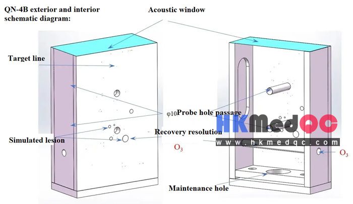
At the center position of the upper panel of the phantom, there are two scanning holes with an inner diameter of 10mm, which are used to insert the intracavitary probe for ultrasound scanning. They are specifically designed to examine the imaging characteristic parameters of the B-ultrasound imaging device that is equipped with an intracavitary ultrasound probe, including blind zone, lateral (transverse) resolution, axial (longitudinal) resolution, lateral geometric position accuracy, axial geometric position accuracy, and the diameter error of the simulated lesion. The left and right side panels of the phantom have probe hole channels for measuring the withdrawal direction resolution and the geometric position accuracy of the withdrawal direction, with an inner diameter of 10mm. The schematic diagram of the appearance and internal structure of the phantom is shown in Figure 1.
1.The four walls and the bottom are made by assembling pieces of plexiglass. The outer surfaces of the four walls are covered with plastic film panels for indication and decoration.
2. The overall dimensions are 210mm (length) × 140mm (width) × 66mm (height).
3. The bottom plate is equipped with a circular hole with a diameter of 36mm, which is sealed with a rubber sheet of 50mm in diameter and 2mm in thickness. This serves as a passage for injecting the maintenance fluid and removing air.
4. The body model is filled with TM material that meets the requirements of national standards as the standard sound transmission medium.
5. On the upper panel of the phantom, there are two central probe access channels with a diameter of φ10mm at 60mm and 120mm from the sound window. These channels are through-hole channels, allowing the probe to be inserted into them for ultrasonic scanning. The left and right side panels of the phantom have probe access channels with an inner diameter of 10mm for measuring the resolution in the retraction direction and the geometric position accuracy of the retraction direction. These channels are through-hole channels running through the left and right side panels, and the internal probe can be inserted through them for scanning.
6. Linear Target System
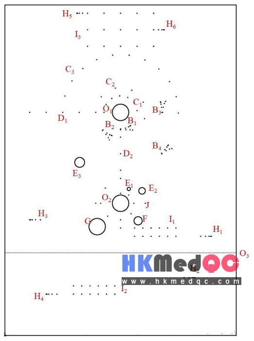
The TM material is embedded with the following target groups
(1) O1-O3 probing holes.
There are two probing holes with a diameter of φ10mm on the upper and lower panels of the phantom, located at the center of the upper and lower halves of the panel respectively. Around probing hole O1, there are axial lateral resolution target groups, lateral target groups, and longitudinal target groups. Around probing hole O2, there are blind zone target groups, imaging geometric distortion target groups, simulated cystic lesions, simulated tumor lesions, simulated cyst and simulated calculus lesions. Probing hole O3 is located on the left and right panels of the phantom, used for measuring the direction resolution and geometric position accuracy of the withdrawal direction. This channel is a through-channel between the left and right panels, and the internal probe can be inserted from the left and right panels for scanning.
(2) A: Blind zone target group.
The blind zone target group is arranged around the probe hole O2. There are a total of 8 target lines, with one set every 45°. The setting depth starts from 1 mm above the center probe hole O2's edge and increases by 1 mm at each step, ranging from 1 mm to 8 mm.
(3) B1 - B4: Axial lateral resolution target group.
The axial lateral resolution target groups are arranged around the probe hole O1. Their lateral branches are respectively located on the circular arcs with radii of 5, 10, 20, and 30 mm from the edge of the central probe hole O1, namely groups B1, B2, B3, and B4. Each target line is distributed on the circular arcs with radii of 10 mm, 15 mm, 25 mm, and 35 mm around the center of the probe hole. The lateral spacing between the centers of two adjacent target lines (the chord length of the distance between the two target lines) is successively 3, 2, 1, and 0.5 mm.
This target group has two adjacent target lines in its axial branches both located within a radius centered on the center of the probe hole. The differences in the radius between the centers of the adjacent target lines and the center of the probe hole are 0.5, 1, 2, and 3 mm respectively. Taking the axial lateral resolution of the target group located at the radius of the probe hole center (i.e., 5 mm from the edge of the probe hole) as an example, the schematic diagram of the distribution of the axial lateral resolution target group is shown in Figure 3. Here, in the axially projected resolution target group, the intervals between the target lines are the straight-line distances of the target lines, while in the lateral resolution target group, the intervals between the target lines are the chord lengths (not the arc lengths of the circle).
(4) C1 - C3: Lateral target group (used to evaluate the lateral (horizontal) geometric position accuracy)
The lateral target groups are arranged around the exploration hole O1, located at 5mm, 10mm, and 30mm from the upper edge of the central exploration hole respectively. Among the C2-C3 target groups, the lateral distance between the centers of the two target lines (the straight-line distance between the two target lines) is 10mm. In the C1 target group, the lateral distance between the centers of the two target lines (the straight-line distance between the two target lines) is 5mm. The target lines are distributed on arcs with radii of 10mm, 15mm, and 35mm around the center of the exploration hole. The lateral target group at 5mm is distributed in a semi-circular shape starting from the horizontal position on the left side of the exploration hole, with a total of 5 target points. The lateral target group C2 at 10mm starts from the horizontal position on the left side of the exploration hole and is distributed in a semi-circular shape, with a total of 4 target points. The lateral target group C3 at 30mm starts from the horizontal position on the left side of the exploration hole and is distributed in a semi-circular shape, with a total of 10 target points.
(5) D1 - D2: Vertical target group
1.The longitudinal target group D1 is arranged around the exploration hole O1. There are 6 target lines within it, located at 5, 10, 20, 30, 40, and 50 mm from the left edge of the central exploration hole O1.
2.The longitudinal target group D2 is arranged around the exploration hole O1, containing a total of 4 target lines, located at 5, 10, 20, and 30 mm below the edge directly beneath the central exploration hole O1.
(6) J: Image geometric distortion target group
The image geometric distortion target group is arranged around the probe hole O2. There are 4 target lines within it, each located at the upper, lower, left, and right corners of a square shape, 10mm away from the edge of the central probe hole O2.
(7) H1 - H4: Detection of the retreat direction resolution target group of the voids
Retract direction resolution This is to examine the minimum distance between two target lines that can display two distinct echo signals when the transducer retracts along the axial direction of the exploration hole. The target groups are arranged near the exploration hole O3. The H1-H4 target groups are located at 5, 10, 15, and 20 mm away from the edge of the central exploration hole O3. The resolution of each group of target groups from the innermost exploration hole to the outermost one is 3, 2, 1, and 0.5 mm respectively.
(8) H5 - H6: Target group for discrimination of the direction of sound window retraction
The target groups H5 and H6 for the direction discrimination of the acoustic window retreat are respectively arranged at a depth of 5mm and 10mm below the acoustic window. The resolution of the H5 target group from the right to the left of the acoustic window is 3, 2, 1, and 0.5mm, while the resolution of the H6 target group from the left to the right of the acoustic window is 3, 2, 1, and 0.5mm. This group of target groups can also be used as the lateral resolution target groups for the side array ultrasonic probe.
(9) I1 - I2: Detection of the geometric position accuracy of the target group for the withdrawal direction of the probe hole
The geometric position accuracy of the withdrawal direction target group is arranged near the probe hole O3. The I1 target group is located 5 and 10 mm away from the edge of the central probe hole O3's channel, while the I2 target group is located 15 and 20 mm away from the edge of the central probe hole O3's channel. The spacing between the target lines of each group is 5 mm.
(10) I3: Geometric position accuracy target group for the sound window retraction direction
The geometric position accuracy of the sound window withdrawal direction is as follows: Target group I3 is arranged at a depth of 5mm, 15mm, and 25mm below the sound window. The target line spacing of target group I3 is 5mm.
7. Simulated Lesion
(1) E1 - E3: Simulated Cyst
The E1-E3 structures are arranged around the exploration hole O2, and three cystic simulated lesions are embedded, all of which are cylindrical in shape, with diameters of 2, 4, and 6 mm respectively. The column axes are all parallel to the target line, and the centers are located at 5, 10, and 30 mm above the edge of the central exploration hole, respectively.
(2) F simulated tumor,
The E1-E3 structures are arranged around the exploration hole O2, located on the right lower side of the central exploration hole. The axis of the simulated tumor is 10 mm away from the edge of the central exploration hole, and it is cylindrical in shape, with a diameter of 5 mm. The column axis is parallel to the target line.
(3) G simulated cyst and stone,
The simulated cyst and stone are arranged around the exploration hole O2. The simulated cyst is cylindrical and located at the horizontal position on the lower left side of the central exploration hole, with a distance of 5 to 15 mm from the edge of the central exploration hole. The diameter is 10 mm, and the column axis is parallel to the target line. The simulated stone is irregular in shape and is located in the middle of the cyst, with the maximum size being approximately 4-6 mm.
At the center position of the upper panel of the phantom, there are two scanning holes with an inner diameter of 10mm, which are used to insert the intracavitary probe for ultrasound scanning. They are specifically designed to examine the imaging characteristic parameters of the B-ultrasound imaging device that is equipped with an intracavitary ultrasound probe, including blind zone, lateral (transverse) resolution, axial (longitudinal) resolution, lateral geometric position accuracy, axial geometric position accuracy, and the diameter error of the simulated lesion. The left and right side panels of the phantom have probe hole channels for measuring the withdrawal direction resolution and the geometric position accuracy of the withdrawal direction, with an inner diameter of 10mm. The schematic diagram of the appearance and internal structure of the phantom is shown in Figure 1.
1.The four walls and the bottom are made by assembling pieces of plexiglass. The outer surfaces of the four walls are covered with plastic film panels for indication and decoration.
2. The overall dimensions are 210mm (length) × 140mm (width) × 66mm (height).
3. The bottom plate is equipped with a circular hole with a diameter of 36mm, which is sealed with a rubber sheet of 50mm in diameter and 2mm in thickness. This serves as a passage for injecting the maintenance fluid and removing air.
4. The body model is filled with TM material that meets the requirements of national standards as the standard sound transmission medium.
5. On the upper panel of the phantom, there are two central probe access channels with a diameter of φ10mm at 60mm and 120mm from the sound window. These channels are through-hole channels, allowing the probe to be inserted into them for ultrasonic scanning. The left and right side panels of the phantom have probe access channels with an inner diameter of 10mm for measuring the resolution in the retraction direction and the geometric position accuracy of the retraction direction. These channels are through-hole channels running through the left and right side panels, and the internal probe can be inserted through them for scanning.
6. Linear Target System
The TM material is embedded with the following target groups
(1) O1-O3 probing holes.
There are two probing holes with a diameter of φ10mm on the upper and lower panels of the phantom, located at the center of the upper and lower halves of the panel respectively. Around probing hole O1, there are axial lateral resolution target groups, lateral target groups, and longitudinal target groups. Around probing hole O2, there are blind zone target groups, imaging geometric distortion target groups, simulated cystic lesions, simulated tumor lesions, simulated cyst and simulated calculus lesions. Probing hole O3 is located on the left and right panels of the phantom, used for measuring the direction resolution and geometric position accuracy of the withdrawal direction. This channel is a through-channel between the left and right panels, and the internal probe can be inserted from the left and right panels for scanning.
(2) A: Blind zone target group.
The blind zone target group is arranged around the probe hole O2. There are a total of 8 target lines, with one set every 45°. The setting depth starts from 1 mm above the center probe hole O2's edge and increases by 1 mm at each step, ranging from 1 mm to 8 mm.
(3) B1 - B4: Axial lateral resolution target group.
The axial lateral resolution target groups are arranged around the probe hole O1. Their lateral branches are respectively located on the circular arcs with radii of 5, 10, 20, and 30 mm from the edge of the central probe hole O1, namely groups B1, B2, B3, and B4. Each target line is distributed on the circular arcs with radii of 10 mm, 15 mm, 25 mm, and 35 mm around the center of the probe hole. The lateral spacing between the centers of two adjacent target lines (the chord length of the distance between the two target lines) is successively 3, 2, 1, and 0.5 mm.
This target group has two adjacent target lines in its axial branches both located within a radius centered on the center of the probe hole. The differences in the radius between the centers of the adjacent target lines and the center of the probe hole are 0.5, 1, 2, and 3 mm respectively. Taking the axial lateral resolution of the target group located at the radius of the probe hole center (i.e., 5 mm from the edge of the probe hole) as an example, the schematic diagram of the distribution of the axial lateral resolution target group is shown in Figure 3. Here, in the axially projected resolution target group, the intervals between the target lines are the straight-line distances of the target lines, while in the lateral resolution target group, the intervals between the target lines are the chord lengths (not the arc lengths of the circle).
(4) C1 - C3: Lateral target group (used to evaluate the lateral (horizontal) geometric position accuracy)
The lateral target groups are arranged around the exploration hole O1, located at 5mm, 10mm, and 30mm from the upper edge of the central exploration hole respectively. Among the C2-C3 target groups, the lateral distance between the centers of the two target lines (the straight-line distance between the two target lines) is 10mm. In the C1 target group, the lateral distance between the centers of the two target lines (the straight-line distance between the two target lines) is 5mm. The target lines are distributed on arcs with radii of 10mm, 15mm, and 35mm around the center of the exploration hole. The lateral target group at 5mm is distributed in a semi-circular shape starting from the horizontal position on the left side of the exploration hole, with a total of 5 target points. The lateral target group C2 at 10mm starts from the horizontal position on the left side of the exploration hole and is distributed in a semi-circular shape, with a total of 4 target points. The lateral target group C3 at 30mm starts from the horizontal position on the left side of the exploration hole and is distributed in a semi-circular shape, with a total of 10 target points.
(5) D1 - D2: Vertical target group
1.The longitudinal target group D1 is arranged around the exploration hole O1. There are 6 target lines within it, located at 5, 10, 20, 30, 40, and 50 mm from the left edge of the central exploration hole O1.
2.The longitudinal target group D2 is arranged around the exploration hole O1, containing a total of 4 target lines, located at 5, 10, 20, and 30 mm below the edge directly beneath the central exploration hole O1.
(6) J: Image geometric distortion target group
The image geometric distortion target group is arranged around the probe hole O2. There are 4 target lines within it, each located at the upper, lower, left, and right corners of a square shape, 10mm away from the edge of the central probe hole O2.
(7) H1 - H4: Detection of the retreat direction resolution target group of the voids
Retract direction resolution This is to examine the minimum distance between two target lines that can display two distinct echo signals when the transducer retracts along the axial direction of the exploration hole. The target groups are arranged near the exploration hole O3. The H1-H4 target groups are located at 5, 10, 15, and 20 mm away from the edge of the central exploration hole O3. The resolution of each group of target groups from the innermost exploration hole to the outermost one is 3, 2, 1, and 0.5 mm respectively.
(8) H5 - H6: Target group for discrimination of the direction of sound window retraction
The target groups H5 and H6 for the direction discrimination of the acoustic window retreat are respectively arranged at a depth of 5mm and 10mm below the acoustic window. The resolution of the H5 target group from the right to the left of the acoustic window is 3, 2, 1, and 0.5mm, while the resolution of the H6 target group from the left to the right of the acoustic window is 3, 2, 1, and 0.5mm. This group of target groups can also be used as the lateral resolution target groups for the side array ultrasonic probe.
(9) I1 - I2: Detection of the geometric position accuracy of the target group for the withdrawal direction of the probe hole
The geometric position accuracy of the withdrawal direction target group is arranged near the probe hole O3. The I1 target group is located 5 and 10 mm away from the edge of the central probe hole O3's channel, while the I2 target group is located 15 and 20 mm away from the edge of the central probe hole O3's channel. The spacing between the target lines of each group is 5 mm.
(10) I3: Geometric position accuracy target group for the sound window retraction direction
The geometric position accuracy of the sound window withdrawal direction is as follows: Target group I3 is arranged at a depth of 5mm, 15mm, and 25mm below the sound window. The target line spacing of target group I3 is 5mm.
7. Simulated Lesion
(1) E1 - E3: Simulated Cyst
The E1-E3 structures are arranged around the exploration hole O2, and three cystic simulated lesions are embedded, all of which are cylindrical in shape, with diameters of 2, 4, and 6 mm respectively. The column axes are all parallel to the target line, and the centers are located at 5, 10, and 30 mm above the edge of the central exploration hole, respectively.
(2) F simulated tumor,
The E1-E3 structures are arranged around the exploration hole O2, located on the right lower side of the central exploration hole. The axis of the simulated tumor is 10 mm away from the edge of the central exploration hole, and it is cylindrical in shape, with a diameter of 5 mm. The column axis is parallel to the target line.
(3) G simulated cyst and stone,
The simulated cyst and stone are arranged around the exploration hole O2. The simulated cyst is cylindrical and located at the horizontal position on the lower left side of the central exploration hole, with a distance of 5 to 15 mm from the edge of the central exploration hole. The diameter is 10 mm, and the column axis is parallel to the target line. The simulated stone is irregular in shape and is located in the middle of the cyst, with the maximum size being approximately 4-6 mm.
SAG: KS107QN-4B,Ultrasonic Tissue Phantom,Diagnostic Imaging Phantom,Ultrasound Performance Test,Tissue Simulation Phantom,Hospital Ultrasound Calibration,Sonographic Phantom,Ultrasound System Validation,Biomedical Test Phantom,Imaging Calibration Model