WEK-WS674 Accelerator M-Area Internal and External Measurement Stand
Mode:WEK-WS674
Type:QA-Phantom
Contact: ken@hkmedqc.com
WEK-WS674 Accelerator M-Area Internal and External Measurement Stand.pdf

WEK-WS674 Accelerator M-Area Internal and External Measurement Stand
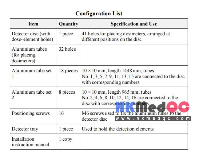
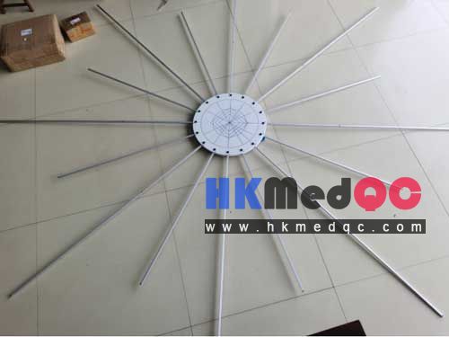
The stand is mainly used to measure leakage radiation inside and outside the
accelerator head M- area. According to the method WS674, thermoluminescent
dosimeters are placed in holes at different positions on the stand to measure leakage
radiation dose. Measurements shall be performed in a phantom. Each side of the
phantom shall be at least 5 cm larger than the radiation field; the depth of the phantom
shall be at least 5 cm greater than the measurement depth. The incident surface shall
be perpendicular to the reference axis and placed at the normal treatment distance.
At the maximum field size, for the given electron energies, measure the dose ratio of
stray X-rays to the total absorbed dose.
Method for Relative Surface Dose Measurement during X- ray
Irradiation
Measurements shall be performed in a phantom. Each side of the phantom shall be at
least 5 cm larger than the radiation field; the depth of the phantom shall be at least
5 cm greater than the measurement depth. The incident surface shall be perpendicular
to the reference axis. The detector shall be placed at the normal treatment distance.
Remove all beam-shaping devices that can be taken off without tools. All flattening
filters shall remain in their designated positions. At the maximum field size, measure
the relative surface dose for each electron energy given in Table 2.
maximum leakage radiation. At all X-ray energies and at the highest electron energy, determine the points
of maximum leakage radiation and measure at these points with the radiation
detector.
Measurement procedure:
Measure at the 41 positions given in Figure A.3 using the radiation detector.
Calculate the percentage value of the average absorbed dose due to leakage
radiation using the average of 24 measurement value
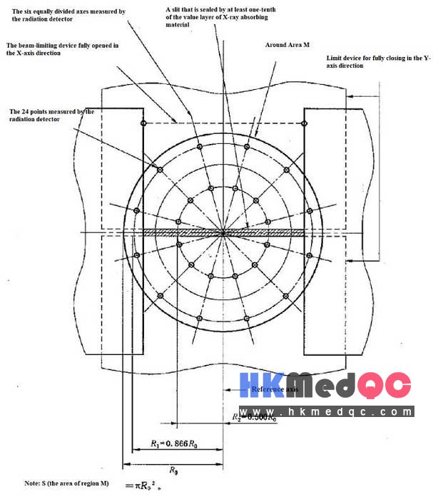
Leakage Radiation through the Beam Limiting Device
X- rays passing through the beam limiting device
Measurement conditions:
Completely shield the radiation exit port with X-ray absorbing material
having at least two tenth- value layers. For non- collapsible beam limiting
devices, measure at the minimum field size.
Use a radiation detector with a cross-section ≤ 1 cm² to measure at the
location of maximum leakage radiation.
Measurements shall be performed at the depth of maximum absorbed dose in a
phantom.Measurement procedure:
Set a rectangular field symmetrically to maximum (X- direction) × minimum
(Y- direction).
Measure at 24 points with the radiation detector, calculate the average, and
determine the percentage relative to the maximum absorbed dose.
Then set the field symmetrically to minimum (X- direction) × maximum
(Y- direction) and repeat the measurement described in step b).
Repeat the above measurements for all X-ray energies.
If a multileaf collimator is used, open the adjustable or interchangeable
collimator to produce a square field of about 300 cm² (approx. 18 cm × 18 cm).
Close the multileaf collimator to the minimum consistent with that field, and
measure the area shielded by the multileaf collimator using the radiation
detector.
Electron beams passing through the beam limiting device
Measurement conditions:
Use 10 mm of tissue- equivalent material as a buildup simulation. For electron
beam applicators / limiting systems of all sizes, at the corresponding
maximum and minimum energies, perform radiography at the normal
treatment distance under the most unfavourable combination of data measured
for the electron energies specified in the type test.
Determine the point of maximum absorbed dose in the region between the line
2 cm outside the geometric field edge and the boundary of the M- area.
Use a radiation detector with a cross-section not larger than 1 cm². The probe
shall have adequate shielding against radiation scattered from material below
the radiation detector.
Measurement procedure:
In the M- area, along the eight dividing lines (see Figure A.2), at intervals of
2 cm, from the point 5 cm outside the geometric field edge to the inner
boundary of the M- area, measure with the radiation detector.
For each electron beam applicator / limiting system, determine the percentage
value of the average radiation detector reading relative to the maximum
absorbed dose at the reference axis at the normal treatment distance.
Leakage Radiation Measurement outside the M- area (neutrons
excluded)
Measurement conditions:
Based on type test results, under the combination of conditions that gives themaximum leakage radiation. At all X-ray energies and at the highest electron energy, determine the points
of maximum leakage radiation and measure at these points with the radiation
detector.
Measurement procedure:
Measure at the 41 positions given in Figure A.3 using the radiation detector.
Calculate the percentage value of the average absorbed dose due to leakage
radiation using the average of 24 measurement value
SAG: WEK-WS674 Accelerator,M-Area Measurement Stand,Linear Accelerator Radiation QA Stand,WS674 TLD dosimetry,X-ray dose ratio test stand,Linac leakage radiation dosimetry stand WS674