KS107QN-4A Endoluminal & Interventional Ultrasound Tissue Mimicking Phantom
Mode:KS107QN-4A
Type:QA-Phantom
Contact: ken@hkmedqc.com
KS107QN-4A Endoluminal & Interventional Ultrasound Tissue Mimicking Phantom.PDF

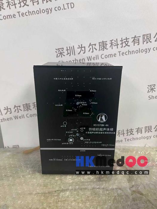
The KS107QN-4A Endocavity Ultrasound Scanning Phantom is a human physical model that mimics tissue in terms of ultrasonic propagation characteristics. It is a test device composed of ultrasonically tissue-mimicking material (referred to as TM material), various embedded test targets (including target lines, simulated cysts, simulated stones, and simulated tumors), acoustic windows, a housing, and an indicative decorative panel.
The top panel of the phantom is provided with through-hole channels (both Φ3mm in diameter) for endocavity probe insertion at 60mm and 120mm from the acoustic window, through which the probe can be inserted for ultrasound scanning.
The left and right side panels of the phantom are equipped with 3mm inner-diameter scanning channels for measuring lateral resolution in the retraction direction and geometric position accuracy in the retraction direction. These channels penetrate the left and right panels, allowing the endocavity probe to be inserted from either side for scanning.
Schematic diagrams of the phantom's appearance and internal structure are shown in Figures.
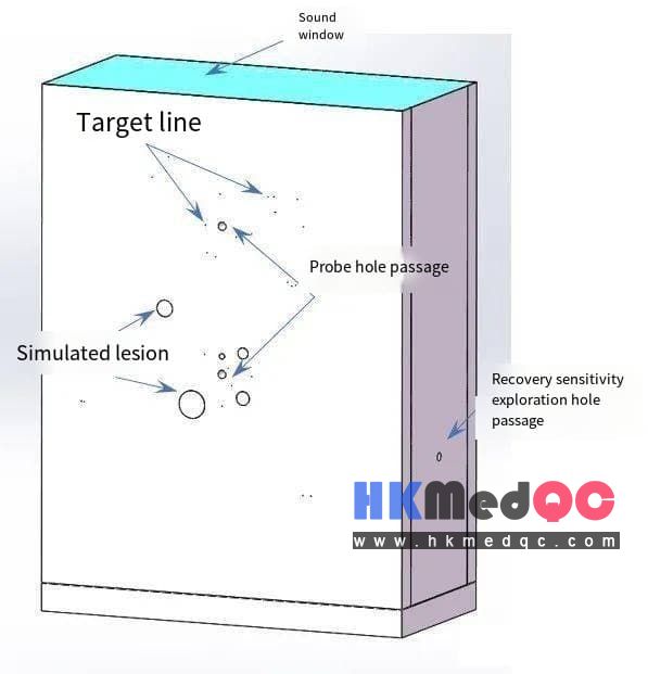
1. The four walls and the bottom are fabricated and assembled from plexiglass. The outer surfaces of the four walls are covered with plastic film panels for indication and decoration purposes.
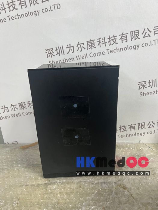
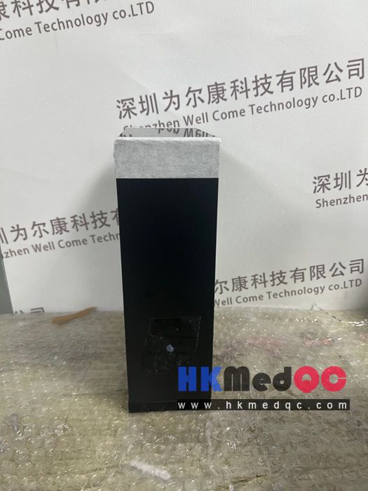
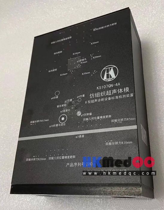
KS107QN-4A Intra-cavity Scanning Ultrasound Model, Real-shot Picture of KS107QN-4A Interventional Scanning Model:
The top panel of the phantom is provided with through-hole channels (both Φ3mm in diameter) for endocavity probe insertion at 60mm and 120mm from the acoustic window, through which the probe can be inserted for ultrasound scanning.
The left and right side panels of the phantom are equipped with 3mm inner-diameter scanning channels for measuring lateral resolution in the retraction direction and geometric position accuracy in the retraction direction. These channels penetrate the left and right panels, allowing the endocavity probe to be inserted from either side for scanning.
Schematic diagrams of the phantom's appearance and internal structure are shown in Figures.
1. The four walls and the bottom are fabricated and assembled from plexiglass. The outer surfaces of the four walls are covered with plastic film panels for indication and decoration purposes.
2. The overall dimensions are 210mm (length) × 140mm (width) × 66mm (height).
3. The bottom plate has a circular hole with a diameter of 36mm and is sealed with a rubber sheet of a diameter of 50mm and a thickness of 2mm, serving as a channel for injecting maintenance fluid and degassing.
4. The body mold is filled with TM material that meets national standards as the standard sound transmission medium.
5. The upper panel of the body mold is 60mm and 120mm away from the sound window respectively. Centered on these positions, there are cavity probe detection holes with a diameter of φ3mm. This channel is a through-hole, and the probe can be inserted into the hole for ultrasonic scanning. The left and right side panels of the body mold have probe detection holes with an inner diameter of 3mm for measuring the resolution of the withdrawal direction and the geometric position accuracy of the withdrawal direction. This channel is a channel running through the left and right side panels, and the cavity probe can be inserted from the left and right side panels for scanning.
6. Line target system
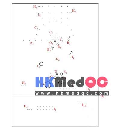
The TM material is embedded with the following target groups, as shown in Figure 2, including:
1) O1-O3 Scanning Holes
Two Φ3mm-diameter scanning holes are provided on the top panel of the phantom, located at the center of the upper half and the center of the lower half of the panel, respectively. Around scanning hole O1, axial-lateral resolution target groups, lateral target groups, and longitudinal target groups are arranged. Around scanning hole O2, dead zone target groups, geometric image distortion target groups, cyst-simulating lesions, tumor-simulating lesions, and cyst-and-stone-simulating lesions are arranged. Scanning hole O3 is located on the left and right side panels of the phantom, used for retraction-direction resolution and retraction-direction geometric position accuracy measurements. This channel penetrates both side panels, allowing the endocavity probe to be inserted from either side for scanning.
2) A: Dead Zone Target Group
The dead zone target group is arranged around scanning hole O2, consisting of 8 target wires placed at 45° intervals. The depth starts at 1mm directly above the edge of the central probe scanning hole O2, with a 1mm step size, at depths of 1, 2, 3, 4, 5, 6, 7, and 8mm.
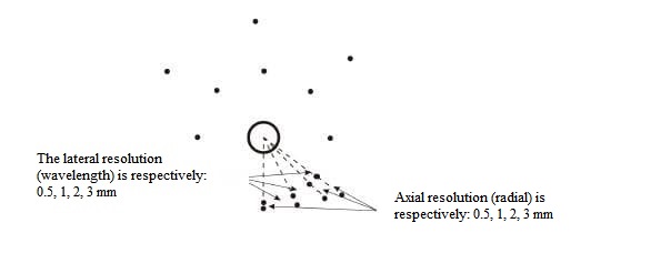
3) B1—B4: Axial-Lateral Resolution Target Groups
The axial-lateral resolution target groups are arranged around scanning hole O1. Their lateral branches are located on arcs at distances of 5, 10, 20, and 30mm from the edge of the central scanning hole O1, corresponding to four groups (B1, B2, B3, B4). The target wires are distributed on arcs with radii of 6.5mm, 11.5mm, 21.5mm, and 31.5mm from the center of the scanning hole. The lateral center-to-center spacing (chord length between adjacent target wires) is 3, 2, 1, and 0.5mm, respectively.
In the axial branches of these target groups, adjacent target wires lie on radii centered at the scanning hole center. The radial difference between adjacent target wires and the scanning hole center is 0.5, 1, 2, and 3mm, respectively. Taking the axial-lateral resolution at 6.5mm radius (i.e., 5mm from the scanning hole edge) as an example, the distribution of the axial-lateral resolution target groups is shown in Figure A.3. All target wire intervals in the axial-lateral resolution target groups are linear distances between wires; in lateral resolution target groups, the intervals are chord lengths (not arc lengths).
4) C1—C3: Lateral Target Groups (for assessing lateral (transverse) geometric position accuracy)
The lateral target groups are arranged around scanning hole O1, at distances of 5mm, 10mm, and 30mm from the upper half edge of the central scanning hole. The lateral center-to-center distance (linear distance between wires) in groups C2–C3 is 10mm.
The lateral center-to-center distance (linear distance between wires) in group C1 is 5mm. Target wires are distributed on arcs with radii of 6.5mm, 11.5mm, and 31.5mm from the scanning hole center. The 5mm lateral target group is semicircularly distributed starting from the left horizontal position of the scanning hole, with 5 targets. The 10mm lateral target group C2 is semicircularly distributed starting from the left horizontal position, with 4 targets. The 30mm lateral target group C3 is semicircularly distributed starting from the left horizontal position, with 10 targets.
5) D1—D2: Longitudinal Target Groups
Longitudinal target group D1 is arranged around scanning hole O1, containing 6 target wires located at 5, 10, 20, 30, 40, and 50mm from the left edge of the central scanning hole O1.
Longitudinal target group D2 is arranged around scanning hole O1, containing 4 target wires located at 5, 10, 20, and 30mm from the directly lower edge of the central scanning hole O1.
6) J: Geometric Image Distortion Target Group
The geometric image distortion target group is arranged around scanning hole O2, containing 4 target wires located at the four vertices of a square, 10mm from the edge of the central scanning hole O2 (up, down, left, right).
7) H1–H4: Retraction Direction Resolution Target Groups at the Scanning Hole
Retraction direction resolution refers to the minimum distance between two target wires that can produce two distinct echo signals when the transducer is retracted axially along the scanning hole. The retraction resolution target groups are arranged near scanning hole O3. Groups H1–H4 are located at 5, 10, 15, and 20mm from the edge of the central scanning hole O3. The resolution of each group, measured from the inside to the outside of the scanning hole, is 3, 2, 1, and 0.5mm, respectively.
8) H5–H6: Retraction Direction Resolution Target Groups at the Acoustic Window
Retraction direction resolution target groups H5–H6 are arranged at depths of 5mm and 10mm below the acoustic window, respectively. For group H5, the resolution from right to left across the acoustic window is 3, 2, 1, and 0.5mm; for group H6, the resolution from left to right across the acoustic window is 3, 2, 1, and 0.5mm. This set of target groups can also be used as lateral resolution targets for linear array ultrasound probes.
9) I1–I2: Retraction Direction Geometric Position Accuracy Target Groups at the Scanning Hole
Retraction direction geometric position accuracy target groups are arranged near scanning hole O3. Group I1 is located at 5 and 10mm from the edge of the central scanning hole O3 channel, while group I2 is located at 15 and 20mm from the edge of the central scanning hole O3 channel. The target wire spacing in each group is 5mm.
10) I3: Retraction Direction Geometric Position Accuracy Target Group at the Acoustic Window
Retraction direction geometric position accuracy target group I3 is arranged at depths of 5mm, 15mm, and 25mm below the acoustic window. The target wire spacing in group I3 is 5mm.
Simulated Lesions
1) E1—E3: Simulated Cysts
Simulated cysts E1—E3 are arranged around scanning hole O2. Three cystic simulated lesions are embedded, all cylindrical with diameters of 2, 4, and 6mm, respectively. Their axes are parallel to the target wires, and their centers are located 5, 10, and 30mm directly above the edge of the central scanning hole.
2) F: Simulated Tumor
The simulated tumor is arranged around scanning hole O2, at the lower right side of the central scanning hole O2. Its axis is 10mm from the edge of the central scanning hole. It is cylindrical with a diameter of 5mm, and its axis is parallel to the target wires.
3) G: Simulated Cyst with Stone
The simulated cyst with stone is arranged around scanning hole O2. The cyst is cylindrical, located horizontally at the lower left side of the central scanning hole O2, between 5~15mm from the hole edge, with a diameter of 10mm and its axis parallel to the target wires. The simulated stone is irregularly shaped, located in the middle of the cyst, with a maximum dimension of approximately 4–6mm.
1) O1-O3 Scanning Holes
Two Φ3mm-diameter scanning holes are provided on the top panel of the phantom, located at the center of the upper half and the center of the lower half of the panel, respectively. Around scanning hole O1, axial-lateral resolution target groups, lateral target groups, and longitudinal target groups are arranged. Around scanning hole O2, dead zone target groups, geometric image distortion target groups, cyst-simulating lesions, tumor-simulating lesions, and cyst-and-stone-simulating lesions are arranged. Scanning hole O3 is located on the left and right side panels of the phantom, used for retraction-direction resolution and retraction-direction geometric position accuracy measurements. This channel penetrates both side panels, allowing the endocavity probe to be inserted from either side for scanning.
2) A: Dead Zone Target Group
The dead zone target group is arranged around scanning hole O2, consisting of 8 target wires placed at 45° intervals. The depth starts at 1mm directly above the edge of the central probe scanning hole O2, with a 1mm step size, at depths of 1, 2, 3, 4, 5, 6, 7, and 8mm.
3) B1—B4: Axial-Lateral Resolution Target Groups
The axial-lateral resolution target groups are arranged around scanning hole O1. Their lateral branches are located on arcs at distances of 5, 10, 20, and 30mm from the edge of the central scanning hole O1, corresponding to four groups (B1, B2, B3, B4). The target wires are distributed on arcs with radii of 6.5mm, 11.5mm, 21.5mm, and 31.5mm from the center of the scanning hole. The lateral center-to-center spacing (chord length between adjacent target wires) is 3, 2, 1, and 0.5mm, respectively.
In the axial branches of these target groups, adjacent target wires lie on radii centered at the scanning hole center. The radial difference between adjacent target wires and the scanning hole center is 0.5, 1, 2, and 3mm, respectively. Taking the axial-lateral resolution at 6.5mm radius (i.e., 5mm from the scanning hole edge) as an example, the distribution of the axial-lateral resolution target groups is shown in Figure A.3. All target wire intervals in the axial-lateral resolution target groups are linear distances between wires; in lateral resolution target groups, the intervals are chord lengths (not arc lengths).
4) C1—C3: Lateral Target Groups (for assessing lateral (transverse) geometric position accuracy)
The lateral target groups are arranged around scanning hole O1, at distances of 5mm, 10mm, and 30mm from the upper half edge of the central scanning hole. The lateral center-to-center distance (linear distance between wires) in groups C2–C3 is 10mm.
The lateral center-to-center distance (linear distance between wires) in group C1 is 5mm. Target wires are distributed on arcs with radii of 6.5mm, 11.5mm, and 31.5mm from the scanning hole center. The 5mm lateral target group is semicircularly distributed starting from the left horizontal position of the scanning hole, with 5 targets. The 10mm lateral target group C2 is semicircularly distributed starting from the left horizontal position, with 4 targets. The 30mm lateral target group C3 is semicircularly distributed starting from the left horizontal position, with 10 targets.
5) D1—D2: Longitudinal Target Groups
Longitudinal target group D1 is arranged around scanning hole O1, containing 6 target wires located at 5, 10, 20, 30, 40, and 50mm from the left edge of the central scanning hole O1.
Longitudinal target group D2 is arranged around scanning hole O1, containing 4 target wires located at 5, 10, 20, and 30mm from the directly lower edge of the central scanning hole O1.
6) J: Geometric Image Distortion Target Group
The geometric image distortion target group is arranged around scanning hole O2, containing 4 target wires located at the four vertices of a square, 10mm from the edge of the central scanning hole O2 (up, down, left, right).
7) H1–H4: Retraction Direction Resolution Target Groups at the Scanning Hole
Retraction direction resolution refers to the minimum distance between two target wires that can produce two distinct echo signals when the transducer is retracted axially along the scanning hole. The retraction resolution target groups are arranged near scanning hole O3. Groups H1–H4 are located at 5, 10, 15, and 20mm from the edge of the central scanning hole O3. The resolution of each group, measured from the inside to the outside of the scanning hole, is 3, 2, 1, and 0.5mm, respectively.
8) H5–H6: Retraction Direction Resolution Target Groups at the Acoustic Window
Retraction direction resolution target groups H5–H6 are arranged at depths of 5mm and 10mm below the acoustic window, respectively. For group H5, the resolution from right to left across the acoustic window is 3, 2, 1, and 0.5mm; for group H6, the resolution from left to right across the acoustic window is 3, 2, 1, and 0.5mm. This set of target groups can also be used as lateral resolution targets for linear array ultrasound probes.
9) I1–I2: Retraction Direction Geometric Position Accuracy Target Groups at the Scanning Hole
Retraction direction geometric position accuracy target groups are arranged near scanning hole O3. Group I1 is located at 5 and 10mm from the edge of the central scanning hole O3 channel, while group I2 is located at 15 and 20mm from the edge of the central scanning hole O3 channel. The target wire spacing in each group is 5mm.
10) I3: Retraction Direction Geometric Position Accuracy Target Group at the Acoustic Window
Retraction direction geometric position accuracy target group I3 is arranged at depths of 5mm, 15mm, and 25mm below the acoustic window. The target wire spacing in group I3 is 5mm.
Simulated Lesions
1) E1—E3: Simulated Cysts
Simulated cysts E1—E3 are arranged around scanning hole O2. Three cystic simulated lesions are embedded, all cylindrical with diameters of 2, 4, and 6mm, respectively. Their axes are parallel to the target wires, and their centers are located 5, 10, and 30mm directly above the edge of the central scanning hole.
2) F: Simulated Tumor
The simulated tumor is arranged around scanning hole O2, at the lower right side of the central scanning hole O2. Its axis is 10mm from the edge of the central scanning hole. It is cylindrical with a diameter of 5mm, and its axis is parallel to the target wires.
3) G: Simulated Cyst with Stone
The simulated cyst with stone is arranged around scanning hole O2. The cyst is cylindrical, located horizontally at the lower left side of the central scanning hole O2, between 5~15mm from the hole edge, with a diameter of 10mm and its axis parallel to the target wires. The simulated stone is irregularly shaped, located in the middle of the cyst, with a maximum dimension of approximately 4–6mm.
KS107QN-4A Intra-cavity Scanning Ultrasound Model, Real-shot Picture of KS107QN-4A Interventional Scanning Model:
SAG: KS107QN-4A,Tissue Equivalent Phantom,Ultrasound Testing Model,Medical Imaging Phantom,Ultrasound QA QC,Tissue Mimicking Phantom,Clinic Ultrasound Calibration,Echo Phantom,Sonography Test Phantom,Ultrasound Device Verification